Opposed blades
Rectangular multileaf dampers for volume flow and pressure control as well as for extremely low-leakage shut-off of ducts and openings in walls and ceiling slabs
Optional equipment and accessories
Application
Special characteristics
Classification
Closed blade air leakage to EN 1751
Test pressure up to 2000 Pa
Test pressure up to 1000 Pa
Nominal sizes
Variants
Construction
Duct connection
Bearings
Blades
Only for steel or stainless steel multileaf dampers with brass or stainless steel bearings (JZ-...-M, JZ-...-E)
Parts and characteristics
Attachments
Accessories
Construction features
Materials and surfaces
Standards and guidelines
Maintenance
Functional description
Multileaf dampers with external linkage can have parallel action blades or opposed action blades.
An external linkage transfers the synchronous rotational movement from the drive arm to the individual blades. Even very large multileaf dampers can be safely opened and closed with this type of linkage.
Opposed action blades close at different speeds since the linkage includes a transverse link. This facilitates the closing process and reduces the closed multileaf damper air leakage.
The torque for closing a multileaf damper must be such that the damper can be safely opened and closed.
For closure, the torque must suffice to ensure complete shut-off by the blades.
Opening is initiated without aerodynamic forces.
When air flows through the damper, the aerodynamic forces of the airflow create a closing force (torque) on the blades; this happens independent of the direction of the airflow. This closing force must be countered, or overcome. The blade position, or blade angle α, for which there is the largest torque depends, among other factors, on the fan characteristics.
Nominal sizes | 200 × 180 mm – 2000 × 1995 mm |
Operating temperature | 0 – 100 °C |
JZ-LL, JZ-LL-A2, minimum torque
180 | 10 | 10 | 10 | 10 | 10 | 10 | 10 | 10 | 10 | 10 |
345 | 10 | 10 | 10 | 10 | 10 | 10 | 10 | 10 | 10 | 10 |
510 | 10 | 10 | 10 | 10 | 10 | 10 | 10 | 10 | 10 | 10 |
675 | 10 | 10 | 10 | 10 | 10 | 10 | 15 | 15 | 15 | 15 |
840 | 10 | 10 | 10 | 10 | 15 | 15 | 15 | 15 | 15 | 15 |
1005 | 10 | 10 | 15 | 15 | 15 | 15 | 15 | 15 | 20 | 20 |
1170 | 15 | 15 | 15 | 15 | 15 | 15 | 20 | 20 | 30 | 30 |
1335 | 15 | 15 | 15 | 15 | 20 | 20 | 30 | 30 | 30 | 30 |
1500 | 15 | 15 | 15 | 20 | 20 | 30 | 30 | 30 | 30 | 30 |
1665 | 20 | 20 | 20 | 20 | 30 | 30 | 30 | 30 | 30 | 30 |
1830 | 20 | 20 | 20 | 20 | 30 | 30 | 30 | 30 | 30 | 30 |
1995 | 20 | 20 | 20 | 20 | 30 | 30 | 30 | 30 | 30 | 30 |
Steel and stainless steel multileaf dampers, free area
180 – 344 | 0.03 | 0.06 | 0.09 | 0.12 | 0.15 | 0.18 | 0.21 | 0.24 | 0.27 | 0.30 |
345 – 509 | 0.06 | 0.11 | 0.17 | 0.23 | 0.28 | 0.34 | 0.40 | 0.45 | 0.51 | 0.57 |
510 – 674 | 0.08 | 0.17 | 0.25 | 0.33 | 0.42 | 0.50 | 0.58 | 0.67 | 0.75 | 0.83 |
675 – 839 | 0.11 | 0.22 | 0.33 | 0.44 | 0.55 | 0.66 | 0.77 | 0.88 | 0.99 | 1.10 |
840 – 1004 | 0.14 | 0.27 | 0.41 | 0.55 | 0.69 | 0.82 | 0.96 | 1.10 | 1.23 | 1.37 |
1005 – 1169 | 0.16 | 0.33 | 0.49 | 0.66 | 0.82 | 0.98 | 1.15 | 1.31 | 1.47 | 1.64 |
1170 – 1334 | 0.19 | 0.38 | 0.57 | 0.76 | 0.95 | 1.14 | 1.33 | 1.52 | 1.72 | 1.91 |
1335 – 1499 | 0.22 | 0.43 | 0.65 | 0.87 | 1.09 | 1.30 | 1.52 | 1.74 | 1.96 | 2.17 |
1500 – 1664 | 0.24 | 0.49 | 0.73 | 0.98 | 1.22 | 1.47 | 1.71 | 1.95 | 2.20 | 2.44 |
1665 – 1829 | 0.27 | 0.54 | 0.81 | 1.08 | 1.36 | 1.63 | 1.90 | 2.17 | 2.44 | 2.71 |
1830 – 1994 | 0.30 | 0.60 | 0.89 | 1.19 | 1.49 | 1.79 | 2.08 | 2.38 | 2.68 | 2.98 |
1995 | 0.32 | 0.65 | 0.97 | 1.30 | 1.62 | 1.95 | 2.27 | 2.60 | 2.92 | 3.25 |
Intermediate sizes: Intermediate widths can be interpolated
Maximum static differential pressure for a closed multileaf damper
Standard construction | 2500 | 2000 | 1650 | 1400 | 1250 | 1100 | 1000 |
Brass bearings (-M) | 3000 | 2500 | 2200 | 1950 | 1750 | 1600 | 1500 |
Stainless steel bearings (-E) | 3000 | 2500 | 2200 | 1950 | 1750 | 1600 | 1500 |
Reinforced blades (-M-V, -E-V) | 3500 | 3000 | 2700 | 2500 | 2300 | 2100 | 2000 |
JZ-LL, JZ-LL-A2, sound power level for a closed multileaf damper
100 | <35 | 35 | 38 | 39 | 41 | 42 | 45 | 48 |
200 | 41 | 42 | 45 | 47 | 48 | 50 | 53 | 56 |
500 | 51 | 52 | 55 | 57 | 58 | 60 | 62 | 65 |
1000 | 58 | 60 | 63 | 64 | 66 | 68 | 70 | >70 |
1500 | 63 | 64 | 67 | 69 | >70 | >70 | >70 | >70 |
2000 | 65 | 67 | 70 | >70 | >70 | >70 | >70 | >70 |
Ducts on both sides
Quick sizing tables provide a good overview of the sound power levels and differential pressures that can be expected. Approximate intermediate values can be interpolated. Precise intermediate values and spectral data can be calculated with our Easy Product Finder design programme.
The sound power levels LWA apply to multileaf dampers with a cross-sectional area (B × H) of 1 m².
The differential pressures apply to multileaf dampers installed in ducts (installation type A).
JZ-LL, JZ-LL-A2, JZ-HL, differential pressure and sound power level
0.5 | <5 | <30 | <5 | <30 | <5 | 7.5 | 22 | 34 | 250 | 63 |
1 | <5 | <30 | <5 | <30 | 8 | 26 | 85 | 53 | 1000 | 83 |
2 | <5 | <30 | <5 | <30 | 30 | 46 | 345 | 73 | >2000 | >90 |
4 | <5 | 41 | 10 | 44 | 120 | 65 | 1385 | >90 | >2000 | >90 |
6 | <5 | 52 | 24 | 56 | 270 | 77 | >2000 | >90 | >2000 | >90 |
8 | 10 | 60 | 42 | 64 | 480 | 85 | >2000 | >90 | >2000 | >90 |
10 | 14 | 67 | 65 | 70 | 750 | >90 | >2000 | >90 | >2000 | >90 |
Rectangular multileaf dampers for volume flow and pressure control as well as for low-leakage shut-off of ducts and openings in walls and ceiling slabs.
Ready-to-operate unit which consists of the casing, aerofoil blades and the blade mechanism.
Flanges on both sides, suitable for duct connection.
The blade position is indicated externally by a notch in the blade shaft extension.
Closed multileaf damper air leakage to EN 1751, class 4.
Casing air leakage to EN 1751, class C.
Special characteristics
Materials and surfaces
Construction
Duct connection
Bearings
Blades
Only for steel or stainless steel multileaf dampers with brass or stainless steel bearings (JZ-...-M, JZ-...-E)
Technical data
Sizing data
Air-regenerated noise
JZ-LL Low-leakage multileaf damper, Closed blade air leakage to EN 1751, classes 3 – 4 No entry: galvanised steel A2 Stainless steel No entry: corner holes on both sides G Flange holes on both sides (no corner holes) No entry: plastic bearings M Brass bearings E Stainless steel bearings Only for steel or stainless steel multileaf dampers with brass or stainless steel bearings V reinforced blades available from width 800 mm No entry: on the right L Left side | B × H H > 1995 = height subdivided Note: width and height subdivided variant, only for galvanised steel No entry: none ER With (only for construction G) No entry: none Z04 – Z07 Quadrant stay Z12 – Z51 Actuators ZF01 – ZF15 Spring return actuators Z60 – Z77 Pneumatic actuators Z1EX, Z3EX Electric Z60EX – Z77EX Pneumatic Only for spring return actuators or pneumatic actuators NO Pressure off/power off to OPEN NC Pressure off/power off to CLOSE No entry: standard construction P1 Powder-coated, specify RAL CLASSIC colour PS Powder-coated, specify DB colour RAL 9010 50 % RAL 9006 30 % All other RAL colours 70 % |
Order example: JZ-LL–G–L/1200×675/ER/ZF06/NC
Material | Galvanised steel |
Duct connection | Flange holes on both sides |
Bearings | Plastic bearings |
Construction of blades | Standard |
Operating side | Left side |
Nominal size | 1200 × 675 mm |
Installation subframe | With |
Attachments | Spring return actuator, 20 Nm, 24 V AC/DC |
Damper blade position | Power off to CLOSE |
Surface | Standard construction |
Multileaf damper with explosion-proof actuator
JZ-LL
Variant
Materials and surfaces
JZ-LL-A2
Variant
Materials and surfaces
Materials
– | Casing | Galvanised sheet steel |
– | Blades | Galvanised sheet steel |
– | Shafts | Galvanised steel |
– | Drive arm | Galvanised steel |
– | Linkage | Galvanised steel |
– | Blade tip seals | Plastic (PP/PTV) |
– | Blade side seals | Closed cell PE foam |
– | Bearings | Plastic |
A2 | Casing | Stainless steel, material no. 1.4301 |
A2 | Blades | Stainless steel, material no. 1.4301 |
A2 | Shafts | Stainless steel, material no. 1.4305 |
A2 | Linkage | Stainless steel, material no. 1.4301 |
E | Bearings | Stainless steel |
M | Bearings | Brass |
Surfaces
– | Casing | Untreated |
P1-RAL ... | Blades | Powder-coated, RAL ... CLASSIC |
PS-DB ... | Blades | Powder-coated, DB ... |
Quadrant stays and limit switches
Z04 | Quadrant stay | – | |
Z05 | Quadrant stay | 1 | Damper blade position CLOSED |
Z06 | Quadrant stay | 1 | Damper blade position OPEN |
Z07 | Quadrant stay | 2 | Damper blade positions CLOSED nad OPEN |
Open/Close actuators
Z12 | SM230A | –1-wire-control –2-wire-control (3-point) | 100 – 240 V AC | 20 Nm | – |
Z13 | GM230A | –1-wire-control –2-wire-control (Open/Close) | 100 – 240 V AC | 40 Nm | – |
Z14 | SM24A | –1-wire-control –2-wire-control (3-point) | 24 V AC/DC | 20 Nm | – |
Z15 | GM24A | –1-wire-control –2-wire-control (Open/Close) | 24 V AC/DC | 40 Nm | – |
Z16 | SM230A | –1-wire-control –2-wire-control (3-point) | 100 – 240 V AC | 20 Nm | S2A |
Z17 | GM230A | –1-wire-control –2-wire-control (3-point) | 100 – 240 V AC | 40 Nm | S2A |
Z18 | SM24A | –1-wire-control –2-wire-control (3-point) | 24 V AC/DC | 20 Nm | S2A |
Z19 | GM24A | –1-wire-control –2-wire-control (3-point) | 24 V AC/DC | 40 Nm | S2A |
Z43 | NM230A | –1-wire-control –2-wire-control (3-point) | 100 – 240 V AC | 10 Nm | – |
Z45 | NM24A | –1-wire-control –2-wire-control (3-point) | 24 V AC/DC | 10 Nm | – |
Z47 | NM230A | –1-wire-control –2-wire-control (3-point) | 100 – 240 V AC | 10 Nm | S2A |
Z49 | NM24A | –1-wire-control –2-wire-control (3-point) | 24 V AC/DC | 10 Nm | S2A |
Minimum torque of multileaf damper has to be considered when selecting the actuator.
Open/Close actuators, fast-running
ZS21 | SMQ24A | –1-wire-control | 24 V AC/DC | 16 Nm | – |
ZS22 | SMQ24A | –1-wire-control | 24 V AC/DC | 16 Nm | S2A |
Only for nominal sizes with a minimum torque not exceeding 16 Nm.
Open/Close actuators, spring return
ZF01 | NF24A | Supply voltage on/off | 24 V AC/DC | 10 Nm | – |
ZF02 | NFA | Supply voltage on/off | 24 – 240 V AC 24 – 125 V DC | 10 Nm | – |
ZF03 | NF24A-S2 | Supply voltage on/off | 24 V AC/DC | 10 Nm | integrated |
ZF04 | NFA-S2 | Supply voltage on/off | 24 – 240 V AC 24 – 125 V DC | 10 Nm | integrated |
ZF06 | SF24A | Supply voltage on/off | 24 V AC/DC | 20 Nm | – |
ZF07 | SFA | Supply voltage on/off | 24 – 240 V AC 24 – 125 V DC | 20 Nm | – |
ZF08 | SF24A-S2 | Supply voltage on/off | 24 V AC/DC | 20 Nm | integrated |
ZF09 | SFA-S2 | Supply voltage on/off | 24 – 240 V AC 24 – 125 V DC | 20 Nm | integrated |
ZF11 | EF24A | Supply voltage on/off | 24 V AC/DC | 30 Nm | – |
ZF12 | EF230A | Supply voltage on/off | 100 – 240 V AC | 30 Nm | – |
ZF13 | EF24A-S2 | Supply voltage on/off | 24 V AC/DC | 30 Nm | integrated |
ZF14 | EF230A-S2 | Supply voltage on/off | 100 – 240 V AC | 30 Nm | integrated |
Minimum torque of multileaf damper has to be considered when selecting the actuator.
Modulating actuators
Z20 | SM24A-SR | 2 – 10 V DC | 24 V AC/DC | 20 Nm | – |
Z21 | GM24A-SR | 2 – 10 V DC | 24 V AC/DC | 40 Nm | – |
Z51 | NM24A-SR | 2 – 10 V DC | 24 V AC/DC | 10 Nm | – |
Minimum torque of multileaf damper has to be considered when selecting the actuator.
Modulating actuators, spring return
ZF05 | NF24A-SR | 2 – 10 V DC | 24 V AC/DC | 10 Nm | – |
ZF10 | SF24A-SR | 2 – 10 V DC | 24 V AC/DC | 20 Nm | – |
ZF15 | EF24A-SR | 2 – 10 V DC | 24 V AC/DC | 30 Nm | – |
Minimum torque of multileaf damper has to be considered when selecting the actuator.
Double acting pneumatic actuators, including explosion-proof actuators
Z60 | Z60EX | DR030 | – | 1.2 – 6 bar | 35 Nm | – | – |
Z61 | Z61EX | DR030 | Power off to close/open | 1.2 – 6 bar | 35 Nm | – | 24 V DC |
Z62 | Z62EX | DR030 | Power off to close/open | 1.2 – 6 bar | 35 Nm | – | 230 V AC |
Z63 | Z63EX | DR030 | – | 1.2 – 6 bar | 35 Nm | 2 | |
Z64 | Z64EX | DR030 | Power off to close/open | 1.2 – 6 bar | 35 Nm | 2 | 24 V DC |
Z65 | Z65EX | DR030 | Power off to close/open | 1.2 – 6 bar | 35 Nm | 2 | 230 V AC |
Z66 | Z66EX | DR060 | – | 1.2 – 6 bar | 70 Nm | – | |
Z67 | Z67EX | DR060 | Power off to close/open | 1.2 – 6 bar | 70 Nm | – | 24 V DC |
Z68 | Z68EX | DR060 | Power off to close/open | 1.2 – 6 bar | 70 Nm | – | 230 V AC |
Z69 | Z69EX | DR060 | – | 1.2 – 6 bar | 70 Nm | 2 | |
Z70 | Z70EX | DR060 | Power off to close/open | 1.2 – 6 bar | 70 Nm | 2 | 24 V DC |
Z71 | Z71EX | DR060 | Power off to close/open | 1.2 – 6 bar | 70 Nm | 2 | 230 V AC |
① Standard
② Explosion-proof (only with brass or stainless steel bearings)
Minimum torque, depending on nominal size of multileaf damper and the operating pressure have to be considered when selecting the actuator.
Single acting pneumatic actuators, including explosion-proof actuators
Z72 | Z72EX | SC060 SO060 | Pressure off to close/open | 6 bar | 30 Nm | ||
Z73 | Z73EX | SC060 SO060 | Power off and pressure off to close/open | 6 bar | 30 Nm | 24 V DC | |
Z74 | Z74EX | SC060 SO060 | Power off and pressure off to close/open | 6 bar | 30 Nm | 230 V AC | |
Z75 | Z75EX | SC060 SO060 | Pressure off to close/open | 6 bar | 30 Nm | 2 | |
Z76 | Z76EX | SC060 SO060 | Power off and pressure off to close/open | 6 bar | 30 Nm | 2 | 24 V DC |
Z77 | Z77EX | SC060 SO060 | Power off and pressure off to close/open | 6 bar | 30 Nm | 2 | 230 V AC |
① Standard
② Explosion-proof (only with brass or stainless steel bearings)
Explosion-proof Open/Close actuators, spring return actuators
Z1EX | ExMax15-SF | 2-wire-control (3-point) | 24 – 240 V AC/DC | 15 Nm | integrated |
Z3EX | ExMax30-SF | 2-wire-control (3-point) | 24 – 240 V AC/DC | 30 Nm | integrated |
Only with brass or stainless steel bearings
Z1EX: Only for nominal sizes with a minimum torque up to 15 Nm.
Illustration shows operating side on the right
JZ-LL, standard sizes
180 | 1 | 90 | 1 |
345 | 2 | 255 | 2 |
510 | 3 | 255 | 2 |
675 | 4 | 255 | 2 |
840 | 5 | 255 | 2 |
1005 | 6 | 255 | 2 |
1170 | 7 | 255 | 2 |
1335 | 8 | 255 | 2 |
1500 | 9 | 255 | 2 |
1665 | 10 | 255 | 2 |
1830 | 11 | 255 | 2 |
1995 | 12 | 255 | 2 |
JZ-LL, intermediate sizes
183 – 343 | 1 | 90 | 1 | 1.5 – 81.5 |
348 – 508 | 2 | 255 | 2 | 1.5 – 81.5 |
513 – 673 | 3 | 255 | 2 | 1.5 – 81.5 |
678 – 838 | 4 | 255 | 2 | 1.5 – 81.5 |
843 – 1003 | 5 | 255 | 2 | 1.5 – 81.5 |
1008 – 1168 | 6 | 255 | 2 | 1.5 – 81.5 |
1173 – 1333 | 7 | 255 | 2 | 1.5 – 81.5 |
1338 – 1498 | 8 | 255 | 2 | 1.5 – 81.5 |
1503 – 1663 | 9 | 255 | 2 | 1.5 – 81.5 |
1668 – 1828 | 10 | 255 | 2 | 1.5 – 81.5 |
1833 – 1993 | 11 | 255 | 2 | 1.5 – 81.5 |
1998 | 12 | 255 | 2 | 1.5 |
JZ, JZ-LL, JZ-HL, weight
180 | 4 | 6 | 8 | 9 | 11 | 13 | 14 | 16 | 18 | 19 |
345 | 6 | 8 | 10 | 12 | 15 | 17 | 19 | 21 | 24 | 26 |
510 | 7 | 10 | 13 | 16 | 19 | 22 | 25 | 27 | 30 | 33 |
675 | 10 | 13 | 16 | 20 | 23 | 27 | 30 | 33 | 37 | 40 |
840 | 11 | 15 | 19 | 23 | 28 | 32 | 37 | 41 | 46 | 50 |
1005 | 11 | 17 | 22 | 27 | 32 | 38 | 43 | 48 | 53 | 59 |
1170 | 13 | 19 | 25 | 31 | 37 | 43 | 49 | 55 | 61 | 67 |
1335 | 15 | 22 | 28 | 35 | 41 | 48 | 55 | 61 | 68 | 74 |
1500 | 16 | 23 | 30 | 37 | 44 | 51 | 59 | 66 | 73 | 80 |
1665 | 17 | 25 | 33 | 41 | 49 | 57 | 65 | 72 | 80 | 88 |
1830 | 18 | 27 | 35 | 44 | 52 | 61 | 69 | 78 | 86 | 95 |
1995 | 19 | 29 | 38 | 47 | 56 | 66 | 75 | 84 | 94 | 103 |
Steel or stainless steel multileaf dampers, width, no. of flange holes per side
200 – 287 | 1 |
288 – 537 | 2 |
538 – 787 | 3 |
788 – 1037 | 4 |
1038 – 1287 | 5 |
1288 – 1537 | 6 |
1538 – 1787 | 7 |
1788 – 2000 | 8 |
Steel or stainless steel multileaf dampers, height, no. of flange holes per side
180 – 211 | 1 |
212 – 461 | 2 |
462 – 711 | 3 |
712 – 961 | 4 |
962 – 1211 | 5 |
1212 – 1461 | 6 |
1462 – 1711 | 7 |
1712 – 1961 | 8 |
1962 – 1995 | 9 |
Shaft end projection
① Standard | 30 | 26 | 30 |
② extended | 250 | 180 | 250 |
③ Square 9 mm | 37 | 37 | 37 |
④ Square 10 mm | 70 | – | 60 |
Installation and commissioning
Width subdivided, width
2550 | 1200 |
2950 | 1400 |
3350 | 1600 |
3750 | 1800 |
4150 | 2000 |
Height subdivided, height
2086 | 1005 |
2416 | 1170 |
2746 | 1335 |
3076 | 1500 |
3406 | 1665 |
3736 | 1830 |
4066 | 1995 |
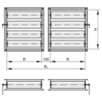
Principal dimensions
B [mm]
Duct width
H [mm]
Duct height
n [ ]
Number of flange screw holes
M [kg]
Weight
Nomenclature
LWA [dB(A)]
A-weighted sound power level of air-regenerated noise for the multileaf damper
α [°]
Damper blade position, 0°: OPEN, 90°: CLOSED
A [m²]
Upstream cross section
v [m/s]
Airflow velocity based on the upstream cross section (B × H)
V [m³/h] and [l/s]
Volume flow rate
Δpst [Pa]
Static differential pressure
Δpst max [Pa]
Maximum static differential pressure
All sound power levels are based on 1 pW.
Share page
Recommend this page
Recommend this page by sending a link by mail.
Share page
Thank you for your recommendation!
Your recommendation has been sent and should arrive shortly.
Contact
We are here for you

Please specify your message and type of request.
Tel.: +44 (0)1842 754545 | Fax: +44 (0)1842 763051
Contact
Thank you for your message!
Your message is send and will be processed shortly.
Our department for Service-Requests will contact you asap.
For general question regarding products or services you can also call:
Tel.: +44 (0)1842 754545 | Fax: +44 (0)1842 763051
Contact
We are here for you
Please specify your message and type of request.
Tel.: +44 (0)1842 754545 | Fax: +44 (0)1842 763051
Contact
Thank you for your message!
Your message is send and will be processed shortly.
Our department for Service-Requests will contact you asap.
For general question regarding products or services you can also call:
Tel.: +44 (0)1842 754545 | Fax: +44 (0)1842 763051


